Chapters
- Build a Migration Strategy
- Customer Migration Scenario – Cisco AireOS Controller or Aruba Wireless Controller to Juniper Mist
- Evaluate Current Deployment
- Migration Steps
Build a Migration Strategy
This document provides a comprehensive look at different methods of migrating from the Legacy Controller based architectures to the Juniper Mist.
To start the process of migration we need to evaluate the current network a customer has and the requirements for the new network. Once we understand the requirements, comes the process for new architecture design. Finally we need to derive a migration plan by selecting an area to evaluate, pilot it and then move to production.
Architecture Migration of Cisco Wireless (AireOS) to Juniper Mist
Customer Migration Options
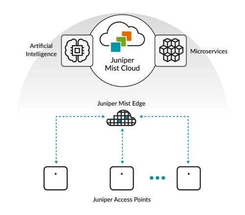
Compared to the traditional need for a wireless LAN controller (WLC) to manage access points, such as the AireOS or Aruba WLC or Juniper mist Access Points are directly managed from the juniper mist Dashboard. This allows customers to manage their wireless networks anywhere, across multiple sites as they now have a single cloud application to manage their networks.
Distributed Data Plane / Local Switching Approach
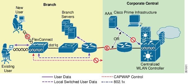
In a Large Campus network leverage a distributed data plane approach, meaning that all the juniper mist access points locally switch all the wireless traffic to the rest of the network. This is like a FlexConnect deployment using a Cisco AireOS.
One of the main benefits of the distributed data plane approach is that it addresses the throughput demands of newer Wi-Fi standards, like Wi-Fi 6E and beyond, since each AP will switch all its wireless traffic locally to the rest of the network.
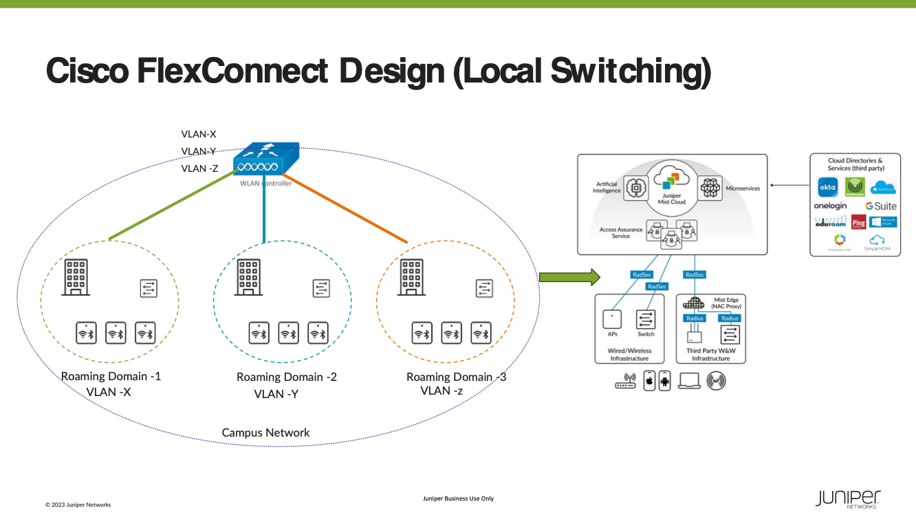
Additionally, since juniper mist leverages the distributed data plane and a cloud-based network, it reduces the amount of equipment that needs to be deployed since, for most cases, a WLC is not required as the mist dashboard manages and monitors all devices in the network.
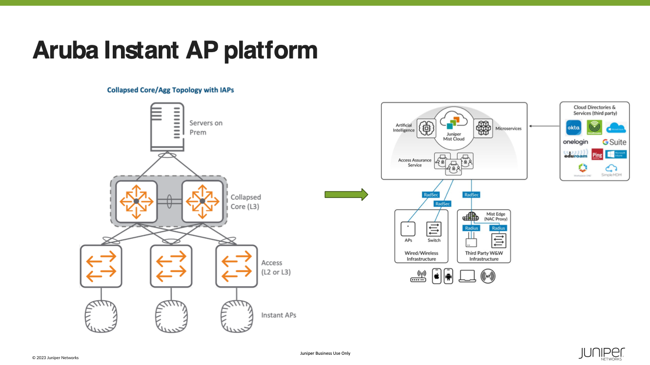
The Aruba Instant AP platform offered enterprise-grade features without requiring a mobility controller. APs within the same subnet form an IAP cluster, configurable through one of the members elected as the conductor. This conductor runs the Virtual Controller (VC) service and could be managed and monitored directly by a web user interface or remotely through Aruba Central or AirWave.
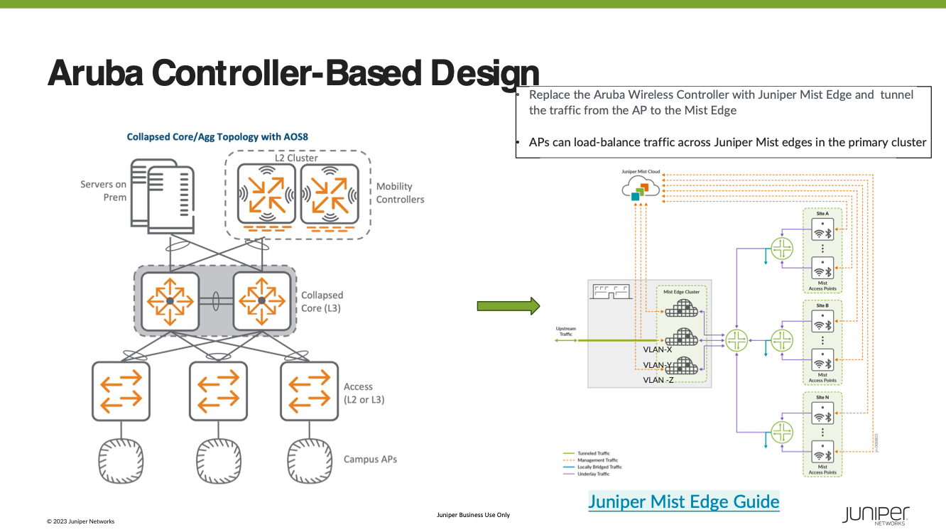
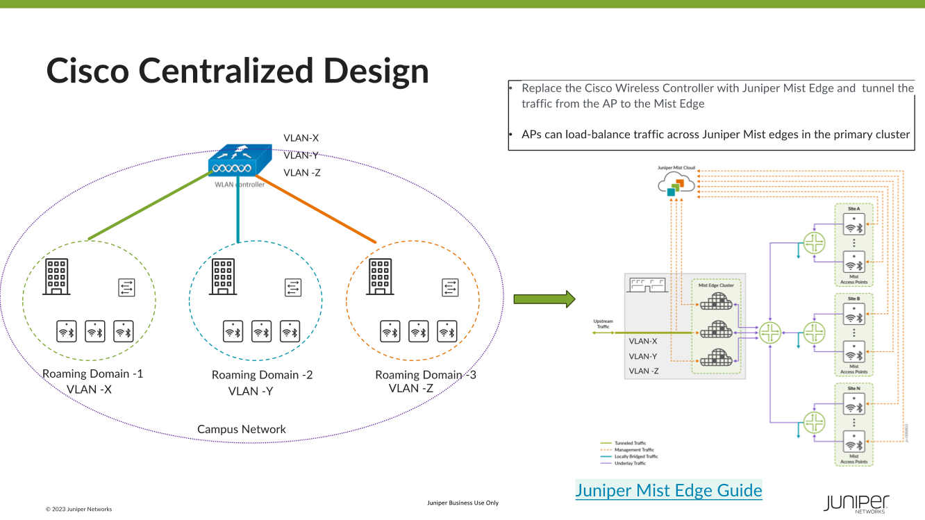
Centralized Data Plan Approach
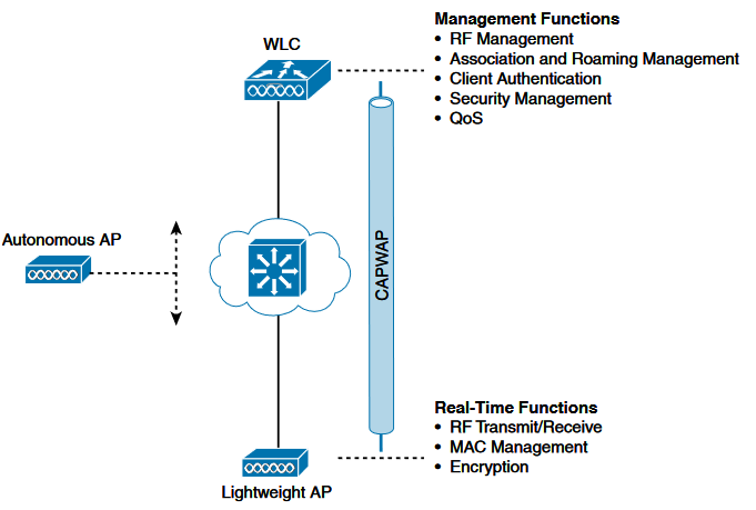
In a controller-based deployment from Cisco or HP Aruba, Wi-Fi client traffic is encapsulated in a CAPWAP or GRE tunnel between the AP and a controller. As traffic from an endpoint reaches the AP over its radio interface, it is encapsulated and forwarded through the wired LAN to the Controller. The controller then inspects the traffic, tags it, and forwards it on a local interface to a trunked user VLAN.
Switching Architecture
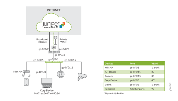
When designing the underlying switching architecture, the ports on the access switches that are connected to the APs follow these recommendations:
- The ports should be configured as trunk ports to allow the APs to pass multiple VLANs when they switch the wireless traffic to the wired network.
- Ensure the VLANs for management traffic for the APs and each broadcasted SSID are allowed on the port.
- For zero-touch provisioning of the ap set the native VLAN on the trunk port to be the management VLAN for the APs.
- Configure the ports with Spanning Tree Portfast Trunk, BPDU guard, and Root guard.
If wired clients are connected to the same switch, the VLANs associated with the wired clients should be confined to that specific access switch (see the example below). VLANs associated with the wireless clients should span across all the access switches that are within the roaming domain.
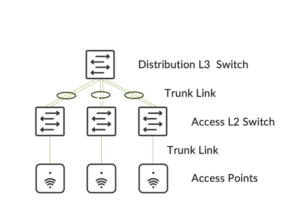
Moving up to the distribution layer switches, it is recommended to configure the distribution switches in either:
- Virtual Chassis/Stacking
- Provides redundancy at the distribution layer with no deliberate layer 2 (L2) loops.
- Uplinks from the access switches to the distribution switch must be configured as trunk ports and in EtherChannel.
- Prune the allowed VLANs on the trunk ports to only the required VLAN.
- HSRP/VRRP
- Provides first-hop redundancy
- STP Root and HSRP primary should be configured on the same switch
- Uplinks will be configured as trunks and EtherChannel
- BPDU and Root Guard on downlinks and Loop Guard on uplinks
- Only the required VLANs should be allowed on trunks to the distribution layer
- The VLANs the wireless clients are placed in when connecting to the WLANs must be allowed on the trunks between the distribution and all the access switches that are part of the roaming domain.
- Please be mindful of asymmetric traffic via the virtual MAC and interface physical MAC which could impact captive portal redirection. It is recommended to use a single gateway MAC
Roaming Domains
A roaming domain is an RF continuity domain with the same SSID where client devices can stay connected no matter where they move within the domain. These can be multiple physical or virtual domains where users would logically move and require fast and seamless roaming to maintain connectivity for their applications.
What does fast and seamless roaming mean?
- Seamless: You have a seamless roam when the client keeps its IP address and policy as it roams across different APs
- Fast: A fast roam happens when a client does not have to re-authenticate every time It roams to a new AP. A fast and secure roam requires keeping the Pairwise Master Key (PMK), derived during the initial authentication, consistent and shared with the roaming domain. This guarantees small delays in roaming, usually less than 50ms. To achieve this, key caching protocols, like 802.11r or OKC, need to be enabled and supported by clients. To further optimize this, networks can take advantage of 802.11k/v.
Roaming domains include groups of floors, a single building, multiple buildings, etc. Whichever physical or virtual groupings are chosen for the roaming domain will affect how the APs are added to Mist Dashboard. Within Mist Dashboard, there are two main management design constructs:
- Organization: A collection of sites that are part of a single organizational
- Sites: Set of juniper devices, their configurations, statistics, and info. This is usually mapped to a geographical location (ex. Sites, groups of buildings, buildings, floors, etc.)

Because of this, it is essential to design the roaming domains to divide the campus’s physical locations with clear RF boundaries, ensuring that clients will roam to APs within the same roaming domains. Examples of finding these divisions can be:
- Geographical Areas: Look for sections of a campus that can be logically carved out. For example, the North, South, East, and West parts of a campus are named as such for a reason.
- Outdoor Wireless: Group outdoor wireless areas within the buildings they’re attached to.
It is recommended to segment the campus by building as the smallest roaming domain. This is due to RF leakage between floors, leading to client devices possibly connecting to APs on different floors. Otherwise, clients might have hard roams within the same building.
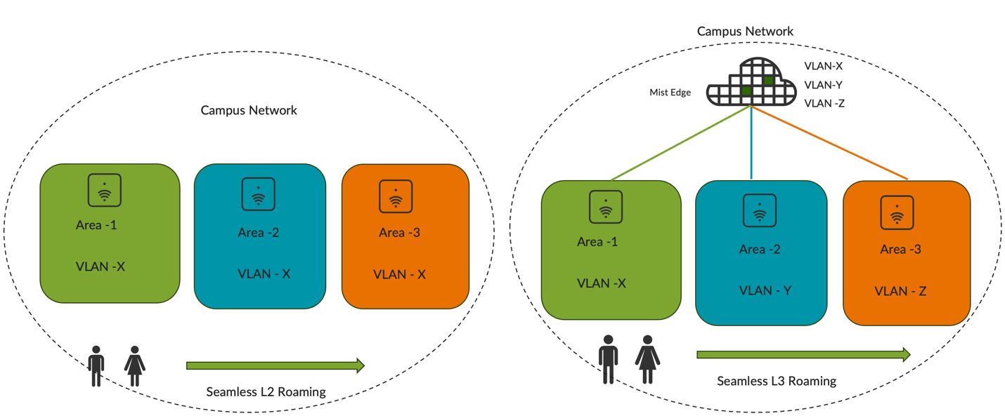
Additionally, it is essential to understand and decide whether there will be Layer 2 (L2) or Layer 3 (L3) roaming for clients when sizing the roaming domain as this will directly be impacted by the underlying switching architecture.
- Layer 2 Roaming: This is when a client roams to another AP where the WLAN is associated with the same VLAN, maintaining its session. This is due to the SSID being the same and on the same VLAN, leading to a seamless roam (same IP address) as well as a fast roam. If clients roam to an AP where the same WLAN is associated with a different VLAN, the session breaks, and the client must eventually re-DHCP, which may take a few seconds.
- Layer 3 Roaming: If clients roam to an AP where the same WLAN is associated with a different VLAN, but there is a mechanism in place (tunneling, re-anchoring to original AP) that allows the client to keep its IP address and hence the roaming will be seamless.
However, having an L2 roam with the same VLAN for the WLAN requires the VLAN to be spanned across all the access switches within the roaming domain, possibly spanning multiple wiring closets or even multiple buildings. Depending on the number of devices in the roaming domain, there may be a requirement for a large subnet for the VLAN, which leads to a large broadcast domain.
The size of this VLAN will be affected by the types of Layer 2 and Layer 3 switches deployed at the site. Their MAC address and ARP table scale, the impact of spanning tree on the CPU, the client scale, the DHCP scope design, and many more will directly impact how large a VLAN can be deployed. The best practices of access network design should be followed.
It’s recommended to keep separate VLANs/subnets for each roaming domain in addition to RF boundaries. This will limit the size of the broadcast domain to that of the roaming domain, limiting the impact of traffic like broadcast, unknown unicast, and multicast (BUM). Also, this will reduce fault and security issues (TCAM/ARP attacks, broadcast storms, etc.). It has the added benefit of simplifying management since the VLAN/subnet can easily locate clients.
Customer Migration Scenario
Migrate to Juniper Mist AP, consider doing a site survey for selecting the right AP and Antenna
- Keep the switch port configuration for the AP as is in case of centralized design
- Replace AP’s in stages and take advantage of new 6GHz band wherever available
- Seamless Roaming is key, select the roaming domain
- Radius integration for client authentication is key
- Disable fast roaming / Rogue AP / Mitigation and Channel planning on installed Cisco /Aruba base
- Validate the client performance is still acceptable
- Define an area that is small enough to be changed in a single change window with as little crossover as possible – a mezzanine floor for example.
- Implement Juniper APs with the same reduced functionality around roaming but leave channel planning on
- Test all client types roaming in and out of the area running live picking sessions
- Define an acceptable failure rate to establish if the phased approach is an option for rollout.
- Test and validate the roaming points at each stage to ensure they meet the agreed thresholds
- Once all APs are Juniper – decide on Mist Edge requirement
- Install Mist Edge pair alongside Cisco controllers mapping clients SSIDs to the same VLANs, keep the access switch config as is
- If Mist Edge not required, then reconfigure edge switches for local breakout
- Enable fast roaming and rogue AP management features on the Juniper Mist platform