Technology Primer: EVPN Multihoming Use Case Overview
Most traditional campus architectures use single-vendor, chassis-based technologies that work well in small, static campuses with few endpoints. However, they are too rigid to support the scalability and changing needs of modern large enterprises. MC-LAG (multi-chassis link aggregation group) is a good example of a single-vendor technology that addresses the collapsed core deployment model. In this model, 2 chassis-based platforms are typically in the core of a customer’s network; deployed to handle all L2/L3 requirements while providing an active/backup resiliency environment. MC-LAG does not interoperate between vendors, creating lock-in, and is limited to 2 devices.
A Juniper Networks EVPN Multihoming solution based on EVPN-VXLAN addresses the collapsed core architecture and is simple, programmable, and built on a standards-based architecture (https://www.rfc-editor.org/rfc/rfc8365) that is common across campuses and data centers.
EVPN Multihoming uses a Layer 3 IP-based underlay network and an EVPN-VXLAN overlay network between the collapsed core Juniper switches. Broadcast, unknown unicast, and multicast, commonly known as BUM (Broadcast, Unknown unicast, and Multicast) traffic, is handled natively by EVPN and eliminates the need for Spanning Tree Protocols (STP/RSTP). A flexible overlay network based on a VXLAN tunnels combined with an EVPN control plane efficiently provides Layer 3 or Layer 2 connectivity. This architecture decouples the virtual topology from the physical topology, which improves network flexibility and simplifies network management. Endpoints that require Layer 2 adjacency, such as IoT devices, can be placed anywhere in the network and remain connected to the same logical Layer 2 network. With an EVPN Multihoming deployment, up to 4 devices are supported all utilizing EVPN-VXLAN. This standard is vendor-agnostic, so you can use the existing access layer infrastructure such as LACP without the need to retrofit this layer of a customer’s network. Connectivity with legacy switches is accomplished with standards-based ESI-LAG. ESI-LAG utilizes standards-based LACP (Link Aggregation Control Protocol) to interconnect with legacy switches.
Benefits of Campus Fabric: EVPN Multihoming
The traditional ethernet switching approach is inefficient because it leverages broadcast and multicast technologies to announce MAC (Media Access Control) addresses. It is also difficult to manage because you need to manually configure VLANs to extend them to new network ports. This problem increases multi-fold when considering the explosive growth of mobile and IoT devices.
EVPN Multihoming’s underlay topology is supported with a routing protocol that ensures loopback interface reachability between nodes. In the case of EVPN Multihoming, Juniper through Mist Wired Assurance, supports eBGP between the Core switching platforms. These devices support the EVPN-VXLAN function as VTEPs (VXLAN Tunnel Endpoint) that encapsulate and decapsulate the VXLAN traffic. VTEP (VXLAN Tunnel Endpoint) stands for VXLAN tunnel endpoint and represents the construct within the switching platform that originates and terminates VXLAN tunnels. In addition, these devices route and bridge packets in and out of VXLAN tunnels as required. This technology
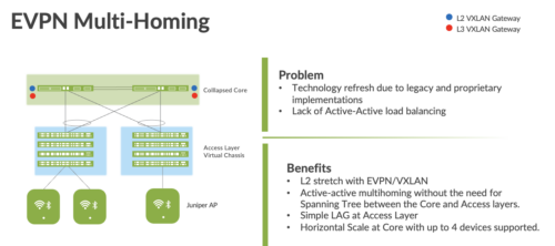
EVPN Multihoming addresses the collapsed core model traditionally supported by technologies like MC-LAG and VRRP. In this case, the customer can retain the investment at the Access layer while supporting the fiber or cabling plant that terminates connectivity up to 4 Core devices
Figure 1 EVPN Multihoming
An EVPN-VXLAN network solves the problems of previous architectures and provides the following benefits:
- Reduced flooding and learning—Control plane-based Layer 2/Layer 3 learning reduces the flood and learn issues associated with data plane learning. Learning MAC addresses in the forwarding plane has an adverse impact on network performance as the number of endpoints grows. This is because more management traffic consumes the bandwidth which leaves less bandwidth available for production traffic. The EVPN control plane handles the exchange and learning of MAC addresses through eBGP routing, rather than a Layer-2 forwarding plane.
- Scalability—More efficient control-plane based Layer 2/Layer 3 learning.
- Loop free built in – EVPN VXLAN mitigates the need for Spanning Tree between the Access and Core layers while supporting active-active load balancing between these layers.
Juniper Mist Wired Assurance
Mist Wired Assurance is a cloud service that brings automated operations and service levels to the Campus Fabric for switches, IoT devices, access points, servers, printers, etc. It is about simplification every step of the way, starting from Day 0 for seamless onboarding and auto-provisioning through Day 2 and beyond for operations and management. Juniper EX Series Switches provide rich Junos streaming telemetry that enable the insights for switch health metrics and anomaly detection, as well as Mist AI capabilities.
Mist’s AI engine and virtual network assistant, Marvis, further simplifies troubleshooting while streamlining helpdesk operations by monitoring events and recommending actions. Marvis is one step towards the Self-Driving Network™, turning insights into actions and fundamentally transforming IT (Information Technology) operations from reactive troubleshooting to proactive remediation.
Mist Cloud services are 100% programmable using open APIs (Application Programming Interfaces) (Application Programming Interface) for full automation and/or integration with your Operational Support Systems, such as: IT applications, such as Ticketing Systems, IP Management Systems, etc.
Juniper Mist delivers unique capabilities for the WAN (Wide Area Network), LAN (Local Area Network) and Wireless networks
- UI (User Interface) or API (Application Programming Interface) driven configuration at scale
- Service Level Expectations (SLE) for key performance metrics such as throughput, capacity, roaming, and uptime.
- Marvis—An integrated AI engine that provides rapid troubleshooting of Full Stack network issues, trending analysis, anomaly detection, and proactive problem remediation.
- Single Management System
- License Management
- Premium Analytics for long term trending and data storageTo learn more about Juniper Mist Wired Assurance please access the following datasheet: https://www.juniper.net/content/dam/www/assets/datasheets/us/en/cloud-services/juniper-mist-wired-assurance-datasheet.pdf
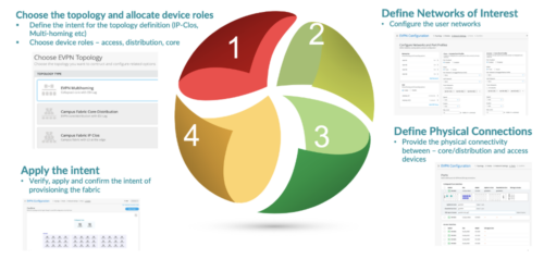
EVPN Multihoming Workflow
EVPN Multihoming, with an EVPN-VXLAN architecture, decouples the overlay network from the underlay network. This approach addresses the needs of the modern enterprise network by allowing network administrators to create logical Layer 2 networks across one or more Layer 3 networks. In an EVPN Multihoming deployment, the use of EVPN VXLAN supports native traffic isolation using routing-instances; commonly called VRFs (Virtual Routing and Forwarding) for macro-segmentation purposes.
The Mist UI workflow makes it easy to create campus fabrics.
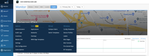
Select the Campus Fabric option, under the Wired Section of the Organization Tab:
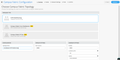
Select EVPN Multihoming and complete the required fields below (default settings suffice):
- Topology Name: The configuration name should represent the Campus Fabric being deployed
- Overlay Settings: Define the BGP AS used to build the Overlay between the Collapsed Core switches
- Underlay Settings: AS Base # used to build the underlay between the Collapsed Core switches. Loopback Prefix # is the subnet defining the number of hosts in the loopback subnet.
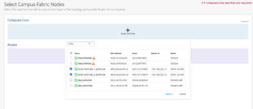
Start by selecting the 2 Collapsed Core switches, in this case we select the 2 QFX 5120-48Y platforms
Next, select the Access switches from the drop-down list. Here, we select the 2 EX4400-48P platforms. Once all switches have been selected, the Mist UI presents the following:
If these devices are being installed for the first time or have not been deployed to date, each Collapsed Core will need a Router ID assigned. The Router ID is used as an identifier when deploying routing protocols such as BGP. In this case, we have existing Router IDs associated with both Collapsed Core platforms show when clicking each Icon. Mist UI also provides chassis information per each platform when clicking the device Icon. The following displays the second Collapsed Core switch’s information including the existing Router ID:
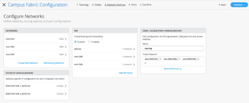
Now we are ready to move to the Network Settings section of the EVPN Multihoming Deployment process by clicking the Continue Button at the upper right-hand corner of the page. The Configure Networks section defines the networks, routing options, and port configurations:
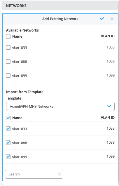
One of the benefits of the Mist UI is the ability to predefine Networks before the EVPN Multihoming deployment. In this case, we select the “AcmeEVPN-MH” Networks template which prepopulates the VLANs that are part of the EVPN Multihoming build.
Once the VLANs are selected, click the check mark at the upper right-hand corner of the drop-down.
The Mist UI provides the following deployment options:
- Configuration of the Subnet/Virtual Gateway instructs the device that it will be acting as the Default Gateway for the specific VLAN/subnet.
- Leaving these options blank allows a 3rd party device such as a Firewall to be used as the Default Gateway or next hop for each VLAN. This allows support for granulate security policies to be implemented where applicable.
- Juniper supports the ability to mix and match requirements – for example, some networks may terminate locally on the core, and some may transit to a firewall for inspection
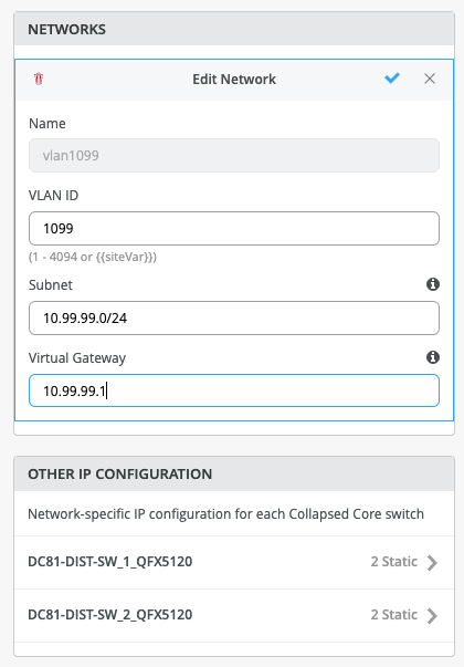
In this case, we assign VLAN IDs, Subnet addresses and Virtual Gateways to each VLAN selected. In this example, we highlight the data per VLAN 1099:
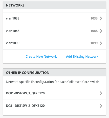
Once all VLANs have been configured, each Collapsed Core switch is automatically assigned IP addresses in each VLAN while sharing the Virtual Gateway address, typically used as a Default Gateway address for each VLAN. The following highlights one of the Collapsed Core’s IP addressing for each VLAN:
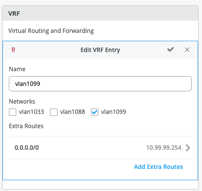
In this example, we choose to isolate each VLAN in its own virtual routing instance. This is due to ACME’s requirement for PCI and granular security policy implementation between VLANs. Under the VRF tab, create a new VRF entry, then associate which VLAN(s) are included in the VRF and if additional routing is required. For example, ACME has decided to utilize an existing Juniper SRX firewall to route between each isolated VRF. This satisfies their security policy enforcement guidelines for traffic patterns between VLANs.
The following illustrates the configuration for VRF named vlan1099. Select the checkmark at the upper right-hand corner of the tab to complete the configuration for each VRF:
Create the ESI LAG port configuration between Collapsed Core switches and Access switches. Use a lowercase naming structure and insure all 3 VLANs are associated:
Inspect each Tab for accuracy before clicking the Continue button. The Mist UI provides the ability to go back to various screens if needed:
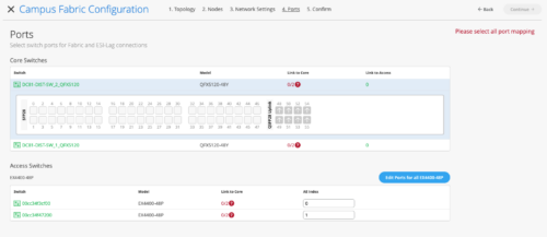
We are in the final stages of deploying the EVPN Multihoming Campus Fabric by selecting which ports are associated between the Collapsed Core switches and between the Collapsed Core and Access switches
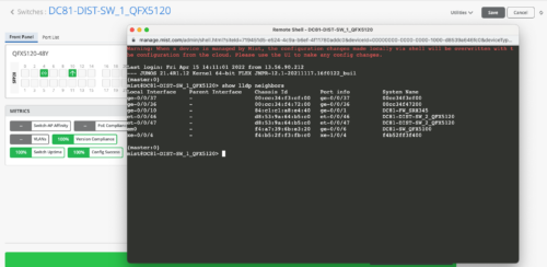
The first step is to select the ports that interconnect each Collapsed Core switch. Assuming all devices are interconnected properly, we can utilize LLDP data per each switch to ascertain port connectivity. For example, the following displays devices connected to Collapsed Core SW1 by selecting the remote shell option under the Utilities section of the switch:
We are now ready to select the ports that interconnect the Collapsed Core Switches.
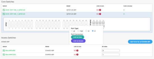
Select each of the core ports off SW1 that connect to SW2.
Ensure Link to Core and the proper port type are selected. In this case, et-0/0/46-47:
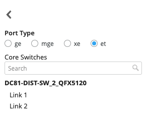
From here, select which local port corresponds to each remote port between Collapsed Cores:
Core ports are shown below, allowing the administrator to clear the selection if needed.
Complete this exercise for the second Collapsed Core and verify:
Now select the ports that connect each Collapsed Core switch to each Access Switch.
In this case, SW1 utilizes ge-0/0/36 to connect to Access 1 and ge-0/0/37 to Access 2.
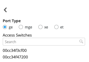
Select ge-0/0/36, Link to Access and port type “ge” then choose the correct Access Switch.
Perform this for both ports.
The same procedure applies for each Access switch.
It is not necessary to know the Collapsed Core remote ports when selecting these uplink ports.
Once all ports have been selected and verified, click the Continue option.
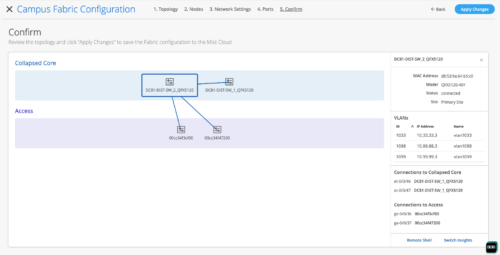
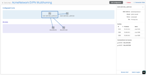
Confirmation of the EVPN Multihoming Build is shown below. Clicking each platform displays the physical topology with requisite data on the right section of the page. Notice, the administrator can access each device through the remote shell option at the lower right corner:
Note: Juniper recommends verification of the EVPN Multihoming Fabric by selecting each switch’s output.
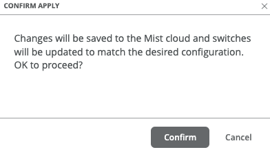
Once all verification is complete, select the Apply Changes option at the right-hand corner of the page. The Mist UI provides the following disclaimer that this new configuration will be applied accordingly:
Finally, the Campus Fabric configuration has been saved to the Mist Cloud which can take up to 10 minutes to complete the configuration push to all elements:
Closing the Campus Fabric Configuration brings the administrator to the Campus Fabric section of the Mist UI.
The user can now access the EVPN Multihoming Campus Fabric:
Notice the Connection Table option at the upper right corner. This provides a layout of the EVPN Multihoming topology as configured and can be used as a source of truth with respect to device inter-connectivity parameters:

